For a long time we have wanted to update GB3KM's audio routing system but had not really come up with a good way to do it...
The problem we have originated when we upgraded GB3KM's Tx to Digital, now we have delays on the audio path which cause issues when using just a single audio channel on the Tx.
The current solution is to have certain channels connected to opposite Left/Right channels of the Tx so the user can select the opposite audio channel to their own.
The new mixer design will automatically map any two input to separate channels rather than being hard wired, it also adds features noted later.
Here is an idea of the components used, i'm not sure if i will actually need buffering on hte input or output for our setup yet.
Mixer_BlockDiagram.JPG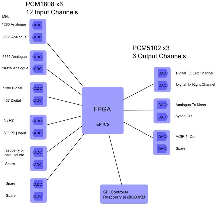
Each of the 12 input channels has a gain control, 32 step linear scaling.
Each of the 6 output channels has a gain control, 32 step linear scaling.
Each output can have any combination of input channels mapped to it.
The first 4 channels have a noise squelch option with a squelch level setting 0-255.
The noise squelch part is the most intensive, it is an FIR High pass filter on each of the inputs which removes most of the voice content and looks for the high frequency noise level to use as the squelch. If the noise level on that channel goes above the threshold then the audio is muted. This is intended for analogue TV receiver paths.
This noise squelch code needs optimising to run on all channels, i have run out of space on the 5k fpga at present right now...
Future enhancements are to have a sub carrier output on the lower two channels, with extra hardware at the user this will allow a user to select one of four audio channels from the repeater rather than just two.
Basically each user ideally monitors one output which is configured to pass all of the active channels but their own.
The interface to the raspberry pi is 'SPI' like, clock, data and chip select connections.
The various configuration bits are loaded in one block at present.
Squelch Info
Here is a screen grab of the audio filter used for the squelch. I initially used 8bit coefficients for the filter but they did not have enough rejection (~40dB) of voice so i had to go to 10bits (~50dB).
Comparison of the filter 10(red) vs 8(blue) bit:
Squelch Filter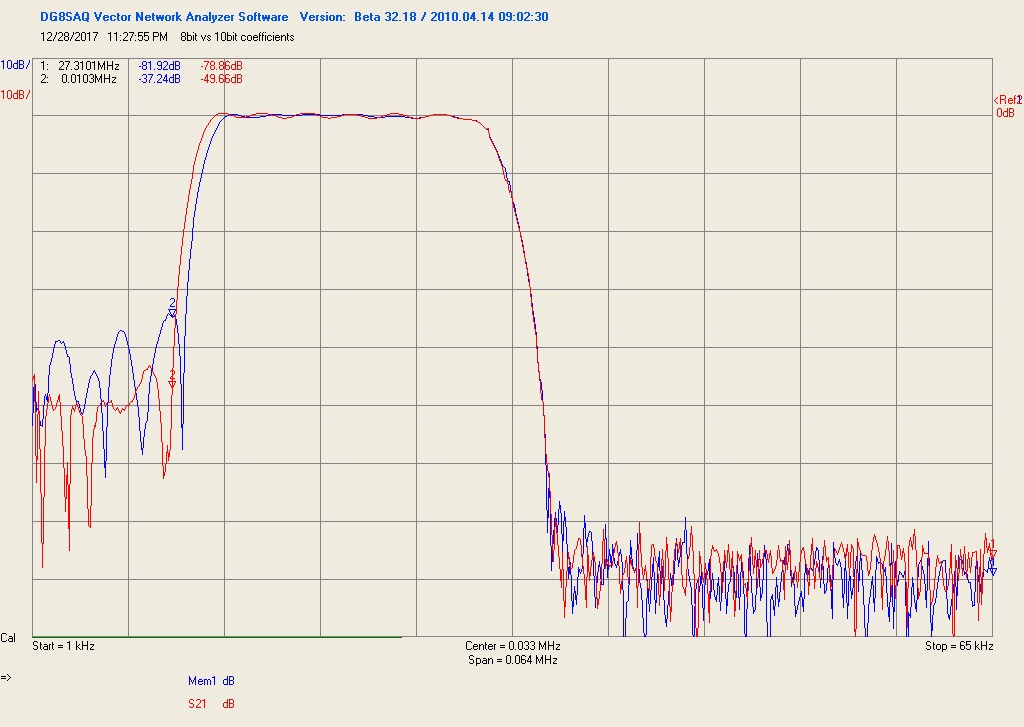
The audio passband for all of the channels is totally flat upto ~30KHz, sample rate is 65KHz.
Testing in Part2


