70cm Up-Converter for DATV
Since starting out on DATV it has been making more sense to use 70cm and hopefully make more DX contacts!. Getting on 70cm DATV using my current setup is very much the same as for the higher bands and only needs a different LO for the transmitter and appropriate 70cm amplifier - see this link for cheap power on 70cm.
I have done quite lot of tests on 70cm now and concluded it is close to impossible to work around the interference from RAF_Fylingdales system on the North Yorkshire moors so 70cm RX is VERY difficult up here! I will still try to work some stations but apologies if it's only one-way!
A 70cm Spectrum plot from home is on the 70cm pages.
Receiving 70cm DATV is a little more of a problem due to the fact that all DVB-S satellite receivers only work above around 900MHz so an up converter is required to get the 70cm signal into the satellite receiver. Old 70cm analogue ATV converters from Microwave Modules or Wood & Douglas are not of any use as they only shift the signal up to about 600MHz and still lower than the satellite receiver range, however they can be modified without much work to get up about 900MHz output.
Recently i was talking to Pat G4EKD and he mentioned that he was using some DirecTV converters for this purpose. I had a look on ebay and they are very widely available from the states at under ?5 each including postage.
These SUP-2400 converters are used to switch between three LNB's from a block to one satellite receiver to cover the different IF outputs. They have a very stable 2400MHz oscillator ideal for DATV but that's no surprise as the modules are meant to be used to receive digital HD video signals. The converters need some modification to get them to work (i could not figure out how the diseqc control works with my receiver!) but it's only an hour's work and a couple of wire links.
Here's what they look like after they have been modified:
LO side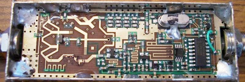
1: Band pass filter- 1400-2150MHz
2: Low pass filter 0-1400MHz
3: Low pass filter 0-800MHz
Filter/control side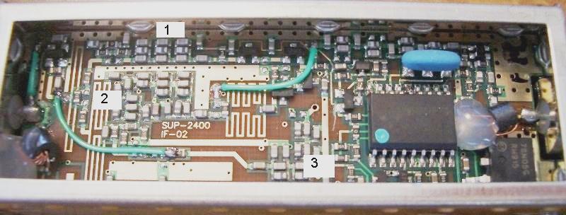
Wire links shown as a green line are fitted to bypass the different filters/switches in the module and improve sensitivity.
Components marked with a green dot need to be removed, the red line shows where the track needs to be cut in the board.
Antenna input modifications to improve sensitivity..
With standard mod's the Noise Figure was 4.5dB, Conversion gain was 18dB
*** If you make the input wire loopy (~15mm long) like the photo and move it close to the tin case the Noise Figure dropped to about 3dB ***
Mods1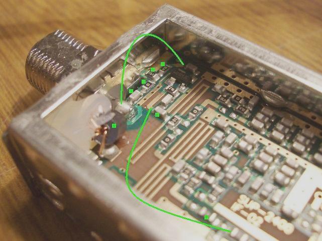
Bypass some of the splitters and diode switching..
Mods2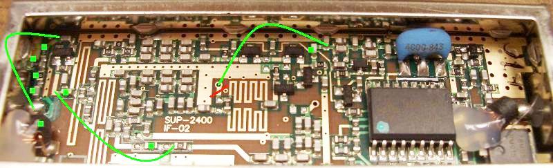
This wire link is fitted to give +5v to the PLL/VCO circuit.
** I have heard about this fail once for some reason and had to wire directly to 5v from regulator.. watch out **
Mods3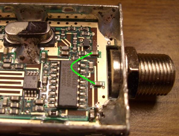
Once converted the module provides a cheap way of receiving 70cm DATV, the sensitivity of this unit on it's own it not that good and a pre-amp will be required at the input from the antenna, but surely you already have one of those if you have done and 70cm ATV before?!
I suppose you could use the pre-amp stage out of a analogue atv converter for this....
------------------------------------------------------------------------------------------------------------------------------------------------------
The alternate method...
thanks to Dan, EI9FHB
Here is a copy of the alternate modification which requires less work. On it's own the converter will not be as sensitive as the mods above but if you use a preamp in front it will be fine.
The modification requires soldering, and quite fine soldering. I would suggest if you have never before soldered then get someone else to do it.
Once you have it, warm up the iron, get out the snips and crack it open.
1
There are two mods.
One is to remove the power going up/down from the converter LNB side. This involves removing a black metal item with wire wrapped around it.
2
The next mod involved either lifting pads of a chip or cutting the legs of the chip nearest the chip itself. Then the wires that were connected to the pads are pulled high by wiring them directly to the 5V regulator onboard.
3
Cut/lift 3 of the pins of the 18pin chip and add 2 wire links.
Pins 14,17,18 need to be cut from the chip or lifted up from the board and the pads where they were attached need to be connected to +5v from the regulator. Pins 17/18 are joined on the pcb already so that's why only 2 wire links.
Lift the three pins marked with arrows away from the pads.. Not very easy but possible !!
A fine tipped soldering iron will make it much easier to just heat and bend them up over. Alternatively using a very small snips cut the leads very close to the black chip body.
Then fit two wires from these pads in green to the output from the 5v regulator.
For pin 14 you can alternatively solder the wire from the regulator to either side of the resistor marked with '0' just above the chip in the photo if it is easier... pin14 pad is very small.
Finally it looks something like this:
4


