After watching a video from Shariar (of The Signal Path) on youtube about a 77GHz adaptive cruise control module for a car i thought i would have a look at one myself.
Link here: https://www.youtube.com/watch?v=8af9YVIqhRk
There are lots of versions of these modules available and little information out there on the web, finding the best one is not possible yet due to price, i picked up a used one off ebay rather cheaply compared to the usual price around ?150 but these cheap ones are rare!
The 77GHz ones appose to the 24GHz ones appear to have '9G768' in the part number but i cant guarantee this!
I used the FCC website and entered some of the fcc numbers there to find out what frequency they operated on.
They usually go in the front of a vehicle bumper to monitor other obstacles as the adaptive cruise control unit, they are well sealed for protection against the weather but the one i bought was easy enough to get into.
There were three pcb's inside, one was the antenna, some sort of dipole array and there was an RF board and a DSP/CAN interface board.
Inside RF Board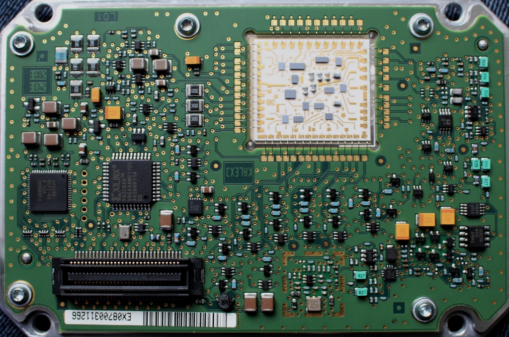
Inside Antenna Board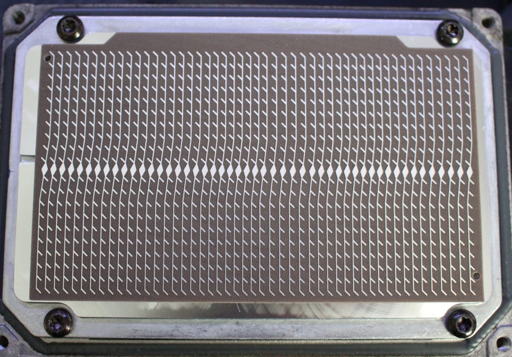
The DSP board is difficult to remove due to it being soldered onto a fixed connector, the RF/Antenna part is either side of an aluminium block.
I have spent a lot of time trying to figure out how the boards work, a lot of it is still unknown but i have some information which maybe useful to anyone else trying to use one of these modules for 76GHz which was my intention :-)
The main high frequency part is on a square substrate around 1" square. All the devices are just bare die soldered down with no markings. This substrate is then wire bonded to the rest of the RF board.
mmWave section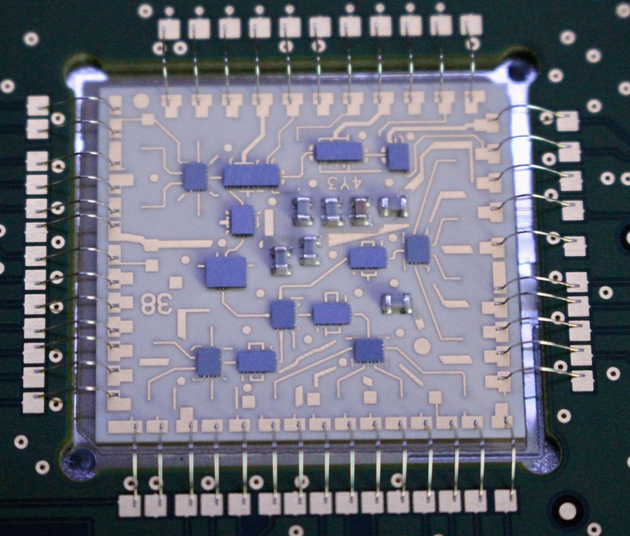
I still have no idea how the original frequency control works as there is no 'regular' PLL ic involved but there is a 1.6GHz reference saw oscillator and a prescaled output of the vco (~19GHz) at around 2.2GHz.
There is a CPLD device is on the board but this does not appear to be used as the PLL because the prescaled output does not route to the chip in any way.
There are 8 rx ports and 4 tx ports to the antenna, rf switches on the RF part are clearly seen.
Here is my best guess at the parts on the mmWave section:
mmWave Best Guess with Voltages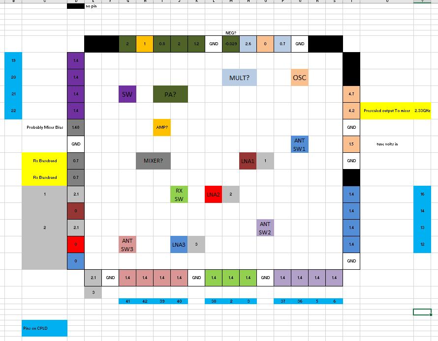
RF Board Header connections:
Header Pin-out so far
I have had a brief look at the CAN Bus data on the second module that i got but no progress has been made here, no idea what's required command wise to enable it.
Antenna gain on narrowest beam is specified as around 20dB and ERP 1.5W so the Tx must be in the region of 10-20mW which would be useful at 76GHz.
Tx:
It appears that 18.99GHz is output from the VCO IC, the next IC multiplies that by two to 37.98GHz, the next IC doubles it again to 75.976GHz and amplifies with some sort of PA.
Rx:
One of 12 antenna ports are selected, an LNA is in place on each of the three (4-way) input paths after the switches, this then feeds into another 3-way switch and then into a quadrature mixer, the LO for the mixer is split off at the output of the PA.
Current status:
I now have a second module with the same internals, slightly different part number.
I have managed to lock the VCO on the unit to 10MHz reference using an ADFxxxx pll from the main board of one of the 3.5G Wimax units available recently.
Phase noise is not great but i can send a carrier at 75.976250 on one unit to the other and the tone is not bad at all.
I have modified the on-board Xilinx chip code to allow external control of all of the antenna switching using spi. I have had varying results so far trying to figure out which is the best antenna selection.
I have tried these units on a path of 11km with no result so far, local tests up to 100m show extremely strong signals.


